
I’m working on a project (see levitum.de) and needed to learn about the design of control surfaces in air vehicles, in particular about Elevator Design. Since my .md file with my notes was sitting in my Obsidian vault and doing nothing I thought I could share my notes and maybe be useful to someone. Everything you find below is grabbed from the great book Aircraft Design (Sadraey). The book is amazing, you could build an entire plane just by reading every amazing chapter, for now, my focus was just Elevators. Some requirements other than what is listed below (such as takeoff requirements) were not important for me since I am interested in eVTOL for my current task. I really enjoyed learning about this topic.
source: Aircraft Design, Sadraey
Design of Control Surfaces
Prerequisites: stability and controllability + handling qualities
- stability -> the inherent tendency of an aircraft to oppose any input and return to the original trim condition if disturbed
- controllability -> Control is the process of changing the aircraft flight condition from an initial trim point to a final or new trim point
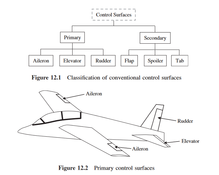
2 groups of surfaces:
- lifting surfaces (wing, horizontal tail, vertical tail) to generate aerodynamic lift
- control surfaces -> action of the pilot
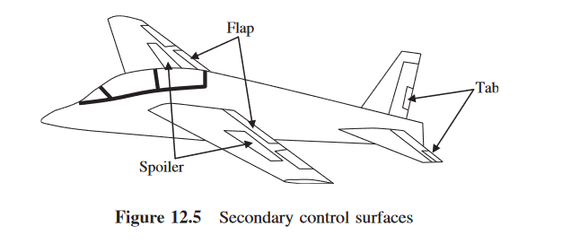
- PRIMARY control surfaces (in charge of control of the flight route)
- Aileron (lateral control, but contribute largely to lateral trim)
- Elevator (longitudinal control, but contribute largely to longitudinal trim)
- Rudder (directional control, but contribute largely to directional trim)
- SECONDARY control surfaces (employed to reinforce primary control surfaces for minor or less important functions)
- Flap (used to increase the wing lift coefficient when the speed is low (i.e., take-off and landing))
- Spoiler (as a brake during landing and as an auxiliary device during roll)
- Tab (its main role is to reduce the force necessary for control by the pilot)
- PRIMARY control surfaces (in charge of control of the flight route)
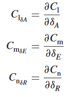
control derivatives -> variables, the rate of change of aerodynamic forces and moments (or their coefficients) with respect to a control surface deflection (e.g., elevator), represent the amount of change in an aerodynamic force or moment acting on an aircraft when there is a small change in the deflection of a control surface. The greater the control derivative, the more powerful is the corresponding control surface.
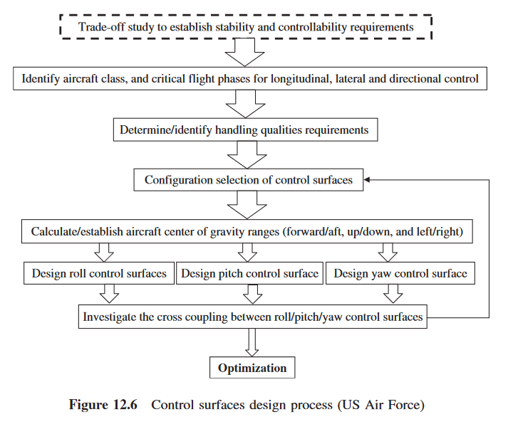
Design Process US Air Force
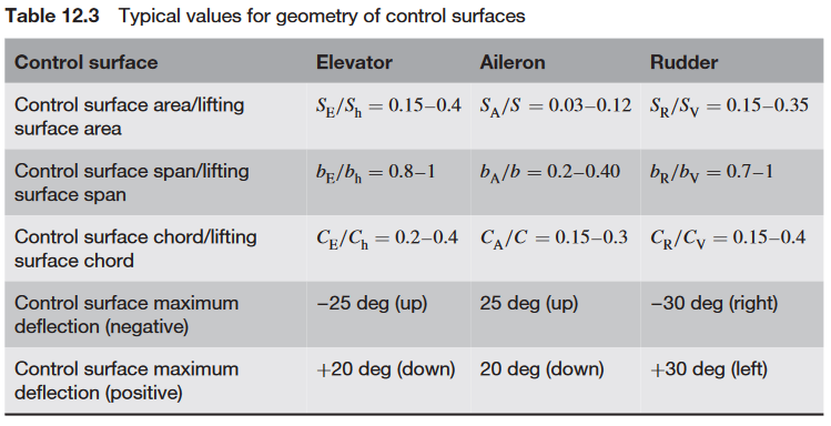
Typical values for geometry of control surfaces
Elevator Design
fundamental requirement -> longitudinal control -> deflection of elevator (δE ) and engine throttle setting (δT )
elevator -> considered as a pitch control device.
how? Since the horizontal tail is located at some distance from the aircraft center of gravity, the incremental lift force creates a pitching moment about the cg.
Pitch control can be achieved by changing the lift on either aft horizontal tail or canard.
2 groups of requirement:
- pilot force
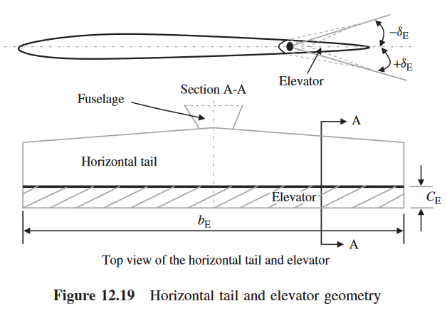
- aircraft response to the pilot input In the design of the elevator, four parameters should be determined. 1) elevator planform area (S_E) 2) elevator chord (C_E) 3) elevator span (b_E) 4) maximum elevator deflection (±δ_Emax)
typical values (up -> -, down -> +) S_E/S_h = 0.15 − 0.4, b_E/b_h = 0.8–1, C_E/C_h = 0.2–0.4, δ_Emax_up = −25 deg and δ_Emax_down = +20 deg
Principles of Elevator Design
The elevator is flap-like and is deflected up and down. With this deflection, the camber of the airfoil of the tail is changed, and consequently the tail lift coefficient (C_Lh ) is changed. The main objective of elevator deflection is to increase or decrease the tail plane lift and hence the tail plane pitching moment.
the following parameters must be determined:
- elevator chord-to-tail chord ratio (C_E/C_h );
- elevator span-to-tail span ratio (b_E/b_h );
- maximum up-elevator deflection (−δ_Emax );
- maximum down-elevator deflection (+δ_Emax );
- aerodynamic balance of the elevator;
- mass balance of the elevator. the first 4 are interrelated
Longitudinal Trim Requirement
Elevator Design Procedure
Design Steps:
- Layout the elevator design requirements (see Section 12.5.2).
- Identify the take-off rotation acceleration requirement from Table 12.9.
- Select the elevator span (see Table 12.3).
- Establish the maximum elevator deflection to prevent flow separation (see Table 12.3).
- Calculate the wing/fuselage lift (Lwf ), aircraft drag (D), and wing/fuselage pitching moment about the wing/fuselage aerodynamic center using Equations (12.62)–(12.64).
- Calculate the aircraft linear acceleration (a) during take-off rotation using Equation (12.55).
- Calculate the contributing pitching moments during take-off rotation (i.e., aircraft weight moment (MW ), aircraft drag moment (MD ), engine thrust moment (MT ), wing/fuselage lift moment (MLwf ), wing/fuselage aerodynamic pitching moment (Macwf ), and linear acceleration moment (M a ) using Equations (12.65)–(12.70). For this calculation, consider the most forward aircraft center of gravity.
- Calculate the desired horizontal tail lift (Lh ) during take-off rotation employing Equation (12.72). For this calculation, consider the most forward aircraft center of gravity.
- Calculate the desired horizontal tail lift coefficient (CLh ) employing Equation (12.73).
- Calculate the angle of attack effectiveness of the elevator (τ e ) employing Equation (12.75). In this calculation, the maximum negative elevator deflection (from step 4) is considered.
- Determine the corresponding elevator-to-tail chord ratio (CE/Ch) from Figure 12.12.
- If the elevator-to-tail chord ratio (CE/Ch) is more than 0.5, it is suggested to select an all-moving tail (i.e., CE/Ch = 1).
- If the angle of attack effectiveness of the elevator (τ e ) is greater than 1, there is no elevator which can satisfy the take-off rotation requirement by the current tail/landing gear specifications. In such a case, the horizontal tail and/or landing gear must be redesigned. Then, return to step 5.
- Using an aerodynamic technique such as computational fluid dynamics or lifting-line theory (see Section 5.14), determine the horizontal tail lift distribution and horizontal tail lift coefficient when the elevator is deflected with its maximum negative angle (i.e., −δE max ).
- Compare the produced horizontal tail lift coefficient of step 13 with the desired horizontal tail lift coefficient of step 9. These two numbers must be the same. If not, adjust the elevator chord or elevator span to vary the produced horizontal tail lift coefficient.
- Calculate the elevator effectiveness derivatives (CmδE , C LδE , C Lhδ E ) from Equations (12.51)–(12.53). For these calculations, examine both the most aft and the most forward aircraft center of gravity.
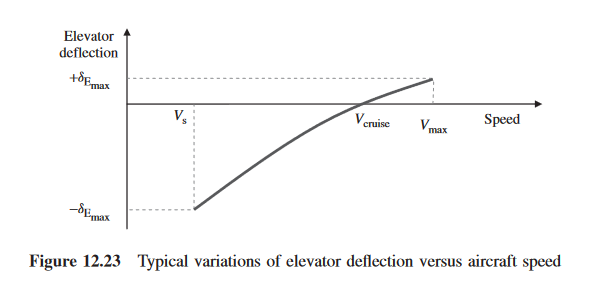
- Calculate the elevator deflection (δE ) required to maintain longitudinal trim at various flight conditions using Equation (12.90). For these calculations, examine the most aft and most forward aircraft center of gravity, as well as various aircraft speeds.
- Plot the variations of the elevator deflection versus airspeed and also versus altitude. For these calculations, consider both the most aft and most forward aircraft center of gravity.
- Compare the maximum required down elevator deflection (+δEmax ) with the maximum deflection established in step 4. If the maximum required down elevator deflection of step 15 is greater than the maximum deflection established in step 4, there is no elevator which can satisfy the longitudinal trim requirements with the current tail/landing gear specification. In such a case, the horizontal tail and/or landing gear must be redesigned. Then, return to step 5.
- Check whether or not the elevator deflection causes the horizontal tail to stall during take-off rotation by using Equation (12.92).
- If tail stall will occur during take-off rotation, the elevator must be redesigned by reducing the elevator deflection and/or elevator chord. Return to step 3.
- If tail stall will occur during take-off rotation, and neither of the two elevator parameters (i.e., elevator deflection and chord) may be reduced to prevent tail stall, other aircraft components such as horizontal tail, landing gear, or aircraft center of gravity must be redesigned/relocated.
- Apply aerodynamic balance/mass balance, if necessary (Section 12.7).
- Optimize the elevator.
- Calculate elevator span, elevator chord, and elevator area then draw the top view and side view of the horizontal tail (including elevator) with dimensions.


