
I found this amazing course in the selection of my University courses. It is a Master’s level course, but I am glad I chose this one even if I am still in my Bachelor’s. I learned how to build and design an Arduino Uno board starting from the selection of the components. I created the schematics, the PCB, the code, and the software for it. I learned about PCB design and how to use a tool like Autodesk Eagle. I developed my soldering skills. And with all of that came also a 1,0. The best grade in the German University System! It’s truly incredible how many possibilities there are! I documented my process with this post. Enjoy!
Introduction & Theory
We all know what electricity is, or at least we have an intuition for it from daily life. Electricity powers these projects. We are now gonna explore some fundamentals that are necessary to understand the project.
Ohm’s law
I=V/R
where I is the current, V is voltage and R is resistance. This is the relationship that explains how our components are working on the board.
Schematics
Schematics are our maps for designing and understanding circuits. We use it to understand which components we need and how they work together. There are a lot of software used for this, I used Autodesk Eagle. We are now going to place and connect the components by reading the datasheets the manufacturers make available.
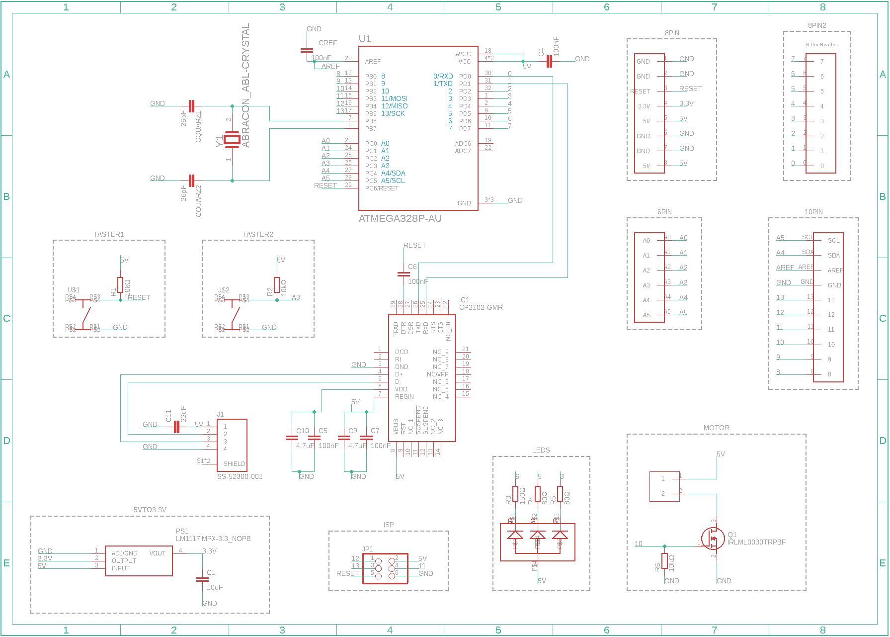
My version for the board’s schematics.
Components and what to keep in mind
There are a few things we have to keep in mind. Below I am going to explain some basics and some other more advanced stuff that isn’t easily readable from datasheets.
-
A resistor is used to reduce current flows and create electrical resistance in an electrical circuit.
-
A capacitor can store electricity by accumulating electric charges. In electronics it is used among other things to flatten the oscillations of voltage and stabilize the power flow. Capacitors of different sizes are appropriate for different current oscillations. The greater the oscillations, the greater the capacity should be. Often we combine more sizes to flatten many sizes of oscillations.
-
A diode is a device used to conduct current in one direction. It is used to tell the otherwise-free-moving electricity in which direction it has to go. This works theoretically by having 0 resistance in one direction and infinite amount of resistance in the other.
-
A LED (Light Emitting Diode) is a special type of diode. It emits light when current flows through it. The emitting color is determined by the amount of energy that flows through it. Every LED in a circuit needs a resistor (ballast resistor). The ballast resistor is used to limit the amount of current that flows through the LED. These are the reasons why every LED color needs a different size resistor.
-
Microcontroller: some people would say the “brain” of our machine. It isn’t a scientifically accurate definition but gives a good idea of its function. It’s the place where the calculations are being done.
-
A transistor can be used as a gain (=to amplify the input signal) and for its switcher function.
-
A quartz is a crystal oscillator/resonator, it is needed by the microcontroller. The frequency of the oscillation is important to keep track of time and provide a stable clock signal.
-
Why do we need RST: RST (=Reset) brings the system in a controlled way to the initial condition, clearing up any errors that might occur. Most systems have a reset line dedicated to this. With a capacitor, we can artificially create at power up a reset button/line for our system. The capacitor turns a change in level into a pulse. We use this capacitor’s characteristics for creating a reset.
-
Why do we need GND: GND (=Ground) is another expression for 0V. Voltage is relative and it is used to explain in relation to this measure the other voltages. We set the 0 level which helps us measure voltage.
-
UART (Universal Asynchronous Receiver-Transmitter) is a device used for communications between microcontroller and other parts. In my case, I implemented a USB/UART converter for easy operation through a USB cable. UART is the middleman between my USB cable and the microcontroller.
-
ISP (In-System Programming), is the ability of devices (microcontroller) to be programmed while installed in a system. Normally we have to first program a chip and then install it. This makes things easier if we want to change the chip or the program. To use this propriety an ISP Header is installed.
-
5V to 3.3V: 5V was the standard for accessories and sensors for hobbyist electronics. Nowadays a lot of the new stuff uses 3.3V. Without the conversion we would damage our accessories.
-
We don’t like undefined: in this electronic world, there are only two possible conditions for a pin to be: high & low or logic 1 & logic 0. States are defined by voltages. From 0V to 0,4V is low. From 2,7V to 5V is high. As you can see there is an undefined region between high and low conditions. To avoid errors (undefined region) we use pull-up resistors and pull-down resistors, where a pull-up resistor is used to deliver a high condition and a pull-down resistor is used to deliver a low condition. In other words, we use pull-up and pull-down to avoid undefined conditions.
-
A switch and a pull-up: We use a pull-up resistor to ensure that no undefined inputs are achieved. By using this resistor the default logical value is 1. This ensures that depending on the position of the switch we got the proper output.
-
A motor, a transistor, its position, and a pull-down: the transistor sits in-between GND (0V) and VCC (5V), this means that one side has a greater amount of voltage/current than the other. This is the reason why it makes much more sense to place the motor (which needs a high amount of current) at the side with more voltage/current. The transistor is able to amplify a small current at the base terminal, (flowing between base and emitter). The small current/voltage at the base can control a much greater current/voltage between the collector and emitter (=VOUT). In addition to that we need to implement a pull-down resistor to the transistor to make sure that in the possibility that an undefined state occurs the motor isn’t running. We only want to run the motor when the pin is high or logical 1.
-
Analog vs digital signals: there are two categories of communication methods. Analog communication is the go-to method for sending complex signals (like the various speed settings for a spinning motor). If you need an on/off signal you will use digital communication, like an on/off control for a button.
PCB
With the schematics we made ourselves a cheat sheet. We made the interactions and relations of the components with each others clear. This next step is about using the scheme we made for the actual board design. We are now deciding where the components are located on the physical board. We are gonna design the circuits and layout. To do this we can use the same software as before, Autodesk Eagle. Following is my design.
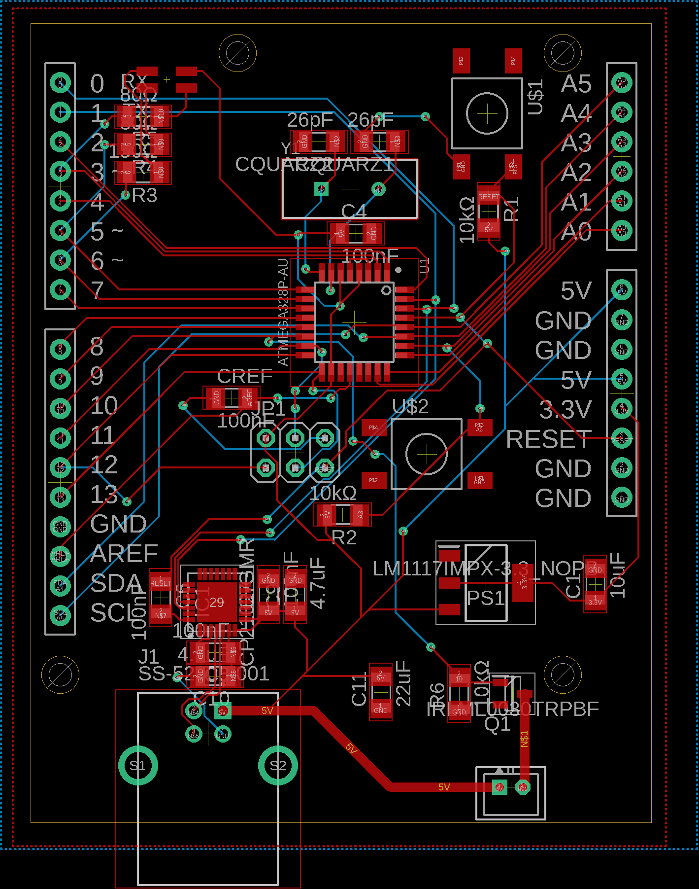
My pcb layout.
Some important rules we need to watch out for when designing a pcb:
- We don’t want any loops that could induce electricity.
- We don’t want any 90 degrees turns in our circuits, to avoid any reflections.
- Capacitors are positioned near the component that needs them.
- Quartz is positioned near its mcu-pins, the 26 pF capacitors for the quartz are placed near it.
- Autodesk Eagle’s Design Rule Check doesn’t show any errors.
Now that the design is done it’s time to order our plate before soldering. You can use something like jlcpcb.com.
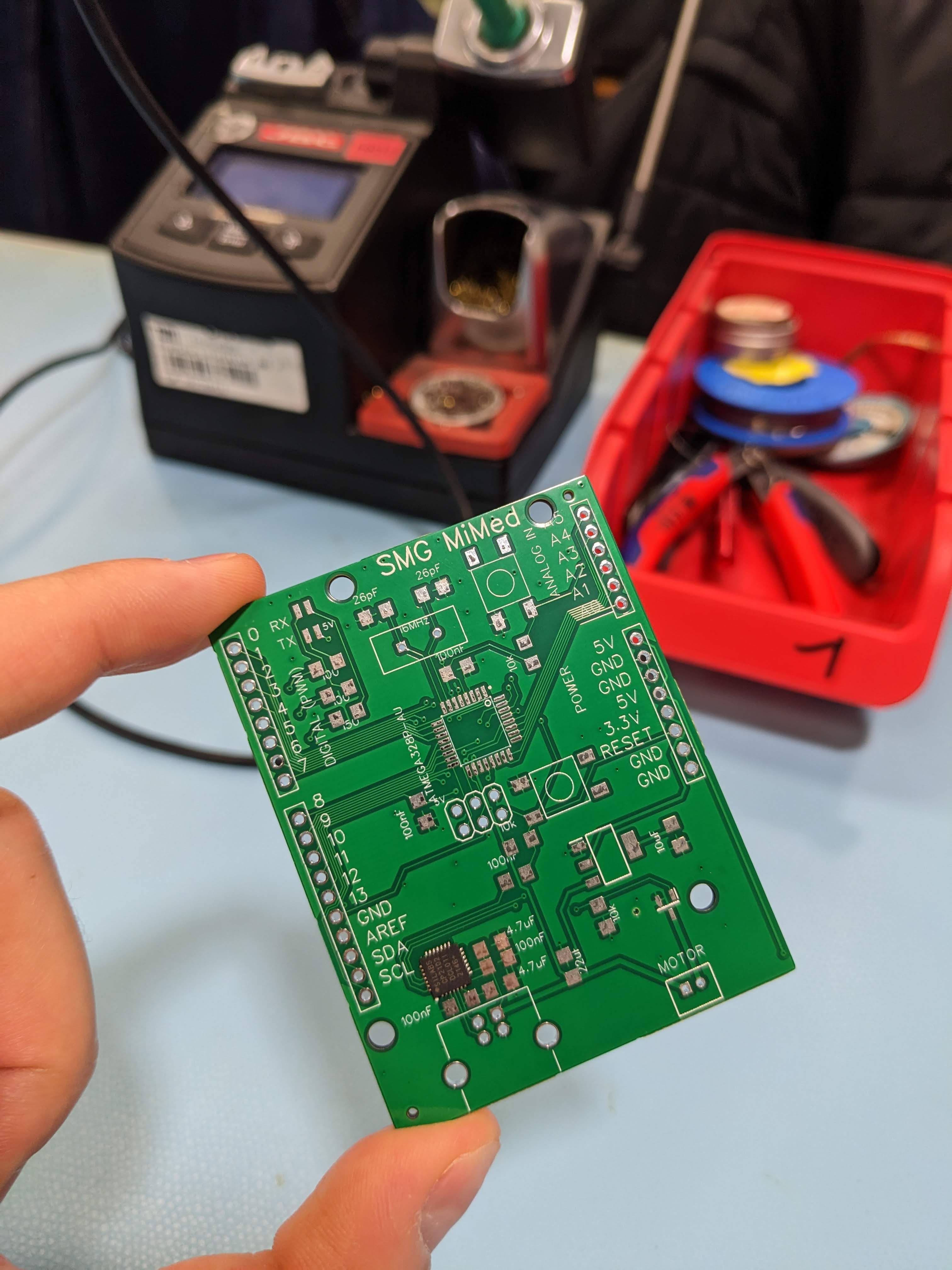
Pic: The naked board. Ready for soldering! :)
Soldering
Soldering was the fun and difficult part. I was looking forward to the hands-on part, but I have to admit, I was intimidated by the microcontroller soldering part. Anyone who has had the opportunity to solder an MCU knows what I am talking about. The pins are so small and they are very fragile. You need a firm hand and precision. Before this difficult part, I soldered the resistors and capacitors and stuff like that. These are easy and comfortable to solder. They are called SMD components (=surface-mount device). The last parts you want to solder are the non-SMD-components. They have pins that go through the board making the plate uneven.
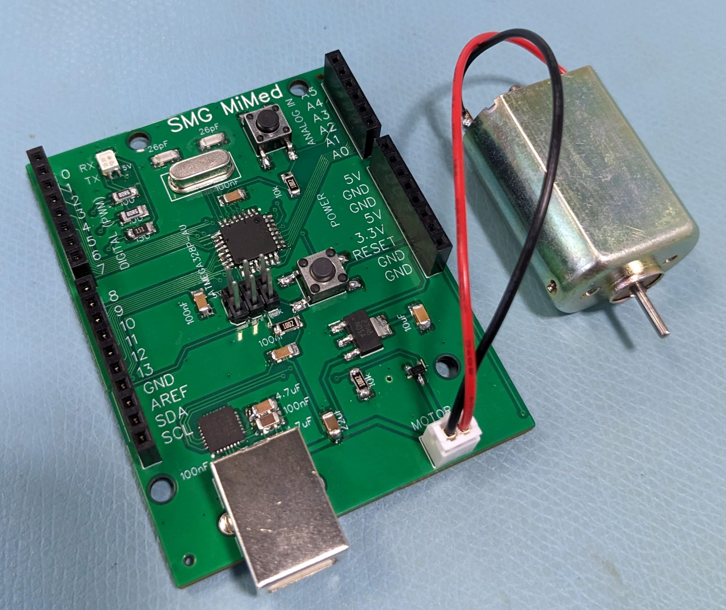
Pic: My soldered and ready to be tested board. A beauty! :)
Software & Code
The last thing to do is to flash the bootloader on the newly installed MCU. Install the Arduino software package and write new programs! I wrote this simple program to check if everything was working. I connected a DC motor to the header and everything was working fine! If you want to try your board with my code, you can find it here on GitHub.
const int motorPin = 10; // make sure you select the right pins!
const int switchPin = A3;
const int LEDonR = 6;
const int LEDonG = 5;

void setup() {
  pinMode(motorPin, OUTPUT);
  pinMode(switchPin, INPUT);
  pinMode(LEDonR, OUTPUT);
  pinMode(LEDonG, OUTPUT);
}

void loop() {
  int switchState = !digitalRead(switchPin);

  if (switchState == HIGH) {
    // Turn on the motor
    digitalWrite(motorPin, HIGH);
    digitalWrite(LEDonR, HIGH);
    digitalWrite(LEDonG, LOW);

  } else {
    // Turn off the motor
    digitalWrite(motorPin, LOW);
    digitalWrite(LEDonG, HIGH);
    digitalWrite(LEDonR, LOW);

  }
}
Your homemade Arduino UNO board is now ready to power your other cool projects!
Conclusion
This was a nice project. I liked the simplicity of things and how you can create awesome projects with relative ease. Things can be done easily, but if you want to, the depth is there and you can explore a lot of themes, starting with the most theoretical electronics or the most complicated robots. There is a lot to learn and I am looking forward to new projects with my personal and newly created Arduino Uno!
And to end on a fun note :))))
Ciao!
GitHub repository
You can check my files at this GitHub link.


