
In this new episode of How I built my own thing from scratch I decided to combine a lot of the good things I learned through my recent times and come up with something I could challenge myself and in the end have an object I could use every day. In this post, you will see how I combined 3D Design, 3D printing, laser cutting, soldering, coding, and much more to come up with this amazing result.

QuattroZero
IMPORTANT: You will find my files and all you need to replicate my result through this link. If you go on building my version or some other make sure to contact me. I want to see your awesome mech keeb!
The Mech Keeb thing
Before deep diving into my project, I think it’s a good idea to get ourselves on the same page. So, what is a mechanical keyboard? The quick answer it’s something like this: mechanical keyboards are an improved and better experience in comparison to your typical cheap office keyboard. Mech Keeb utilizes mechanical switches, tuned stabilizers, high-quality plastic for the keycaps, and much more intentionality in the typing experience. All of this is done to achieve the most pleasurable experience when typing. Nowadays we are investing a lot of time sitting in front of a PC, therefore, I think it’s a good idea to invest some time in high-quality gadgets like a keyboard and mouse to create a better environment while typing. If all of this resonates with you I encouraged you to check the subreddit r/MechanicalKeyboards to take a look at the numerous alternatives there are in this world. Now let’s get to the good stuff.
My choices
For this project, I decided to go with a hand-wired, stacked acrylic, tactile, ortho-linear 40% keyboard with PBT keycaps. Let’s break this down.
- hand-wiring: normal keyboards have a PCB (= circuit board) for controlling the electronics. I already learned about the process of creating a PCB in this other post of mine, for this one I wanted to try this other method. It consists of creating a matrix with the wire through the switches and with the help of diodes and a small board like an Arduino you can substitute having to print a circuit.
- stacked acrylic: this is one of the numerous methods for creating a case for your keyboard. The goal is to use many layers of acrylic sheets (in my case I used plexiglass) to come up with a container for your other hardware. Just like 3D printing, but we are using 5 or 6 layers instead of hundreds.
- tactile: it refers to the switches, the mechanism that actuates the press of the key. There are linear, tactile, and clicky switches. For each of these three macroarea, there are an infinite amount of possibilities so you can choose the sound and feel you are looking for. I used a tactile switch: Akko CS Lavender Purple.
- ortho-linear 40%: this is infos about the layout. Ortholinear means that every key is positionated like in a matrix, everything is symmetrical and each key sits on top of the other. Normal keyboards have each row shifted by a bit. This comes from the early days of typewriters where each key mechanism needed space and therefore each key could not sit on top of each other. Nowadays there isn’t this necessity anymore and the ortho layout should be more natural and comfortable to type on while touch typing. I’m eager to try this layout. 40% means a smaller format where some keys are missing. You can still type every character with the help of macros, shortcuts, and some software.
- PBT keycaps: to achieve a better sound and feel a better PBT plastic is used. Often a more thicker keycaps provide a better sound.
The Story
Now it’s time to illustrate my journey and how it all came to be.
The Design
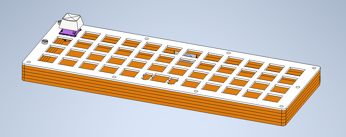
My 3D-model in Inventor.
I started in AutoDesk Inventor, my go-to 3D Design software. To create a stacked acrylic keyboard I thought in layers: the most important being the plate, at whom all the keys are fixed. On the plate, I designed the cut-outs for the keys and stabilizers. I used this datasheet from Cherry MX to make sure I used all the right dimensions and tolerances. This is vital to achieve a working result.
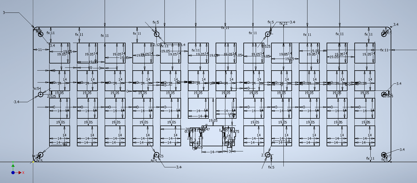
My sketch of the plate with its dimensions.
After the plate, I went down the layers and designed the other levels. I made sure I got a good way of bolting everything together with M3 bolts and nuts. I was quite happy with the result. It was also important, to make it look fancier, to have a cut-out for the USB C connection. I decided I would print a hub to make everything look good and tight.
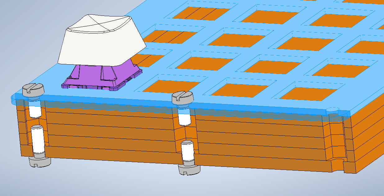
My mounting concept: A nut in the middle and bolts at each side. I designed the cut-offs in the plexiglass to house the bolts.
The Software
The firmware we are going to flash on our microcontroller is written in C and following some guidelines makes everything easier. You have to check out QMK, an awesome open-source tool with a big and helpful community. You’ll find numerous guides on how to create the perfect firmware for your keyboard.
This below is my keymap.c file for my QuattroZero. The core file in every config looks something like this. It looks intimidating but it’s pretty simple. We are declaring different states and layers and explaining how they are constituted.
The Manufacturing
The hands-on part. Let’s begin!
Laser-Cutting
I created laser-cutting machine compatible files with the help of Inventor and proceeded to cut my layers. I learned it is vital to ensure a good quality cut that you make a lot of tests. I got the quality I needed with the help of some experienced friends - Thanks Andrew! :)
Look at this beauty! My logo’s engraving is my favorite part.
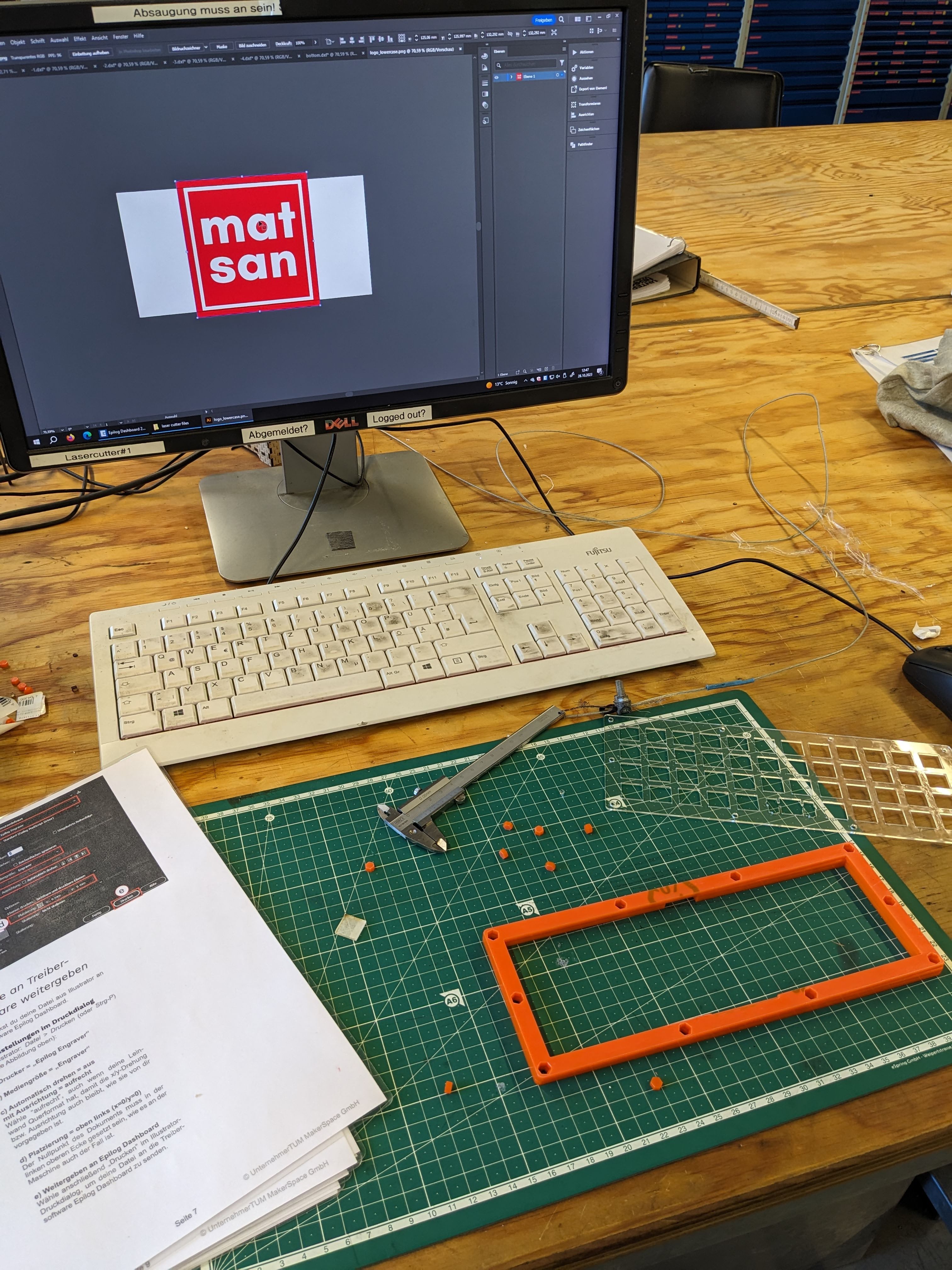
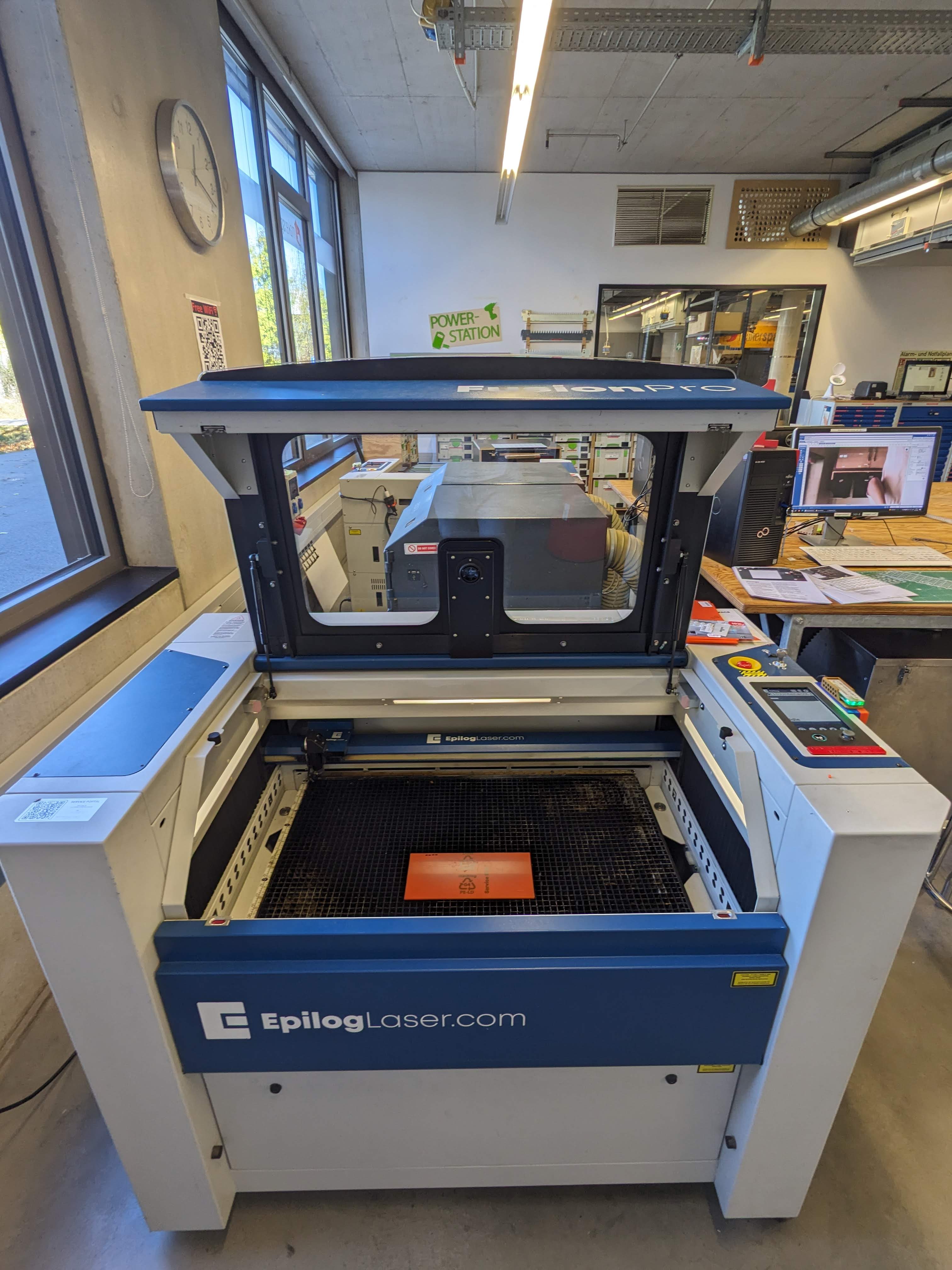

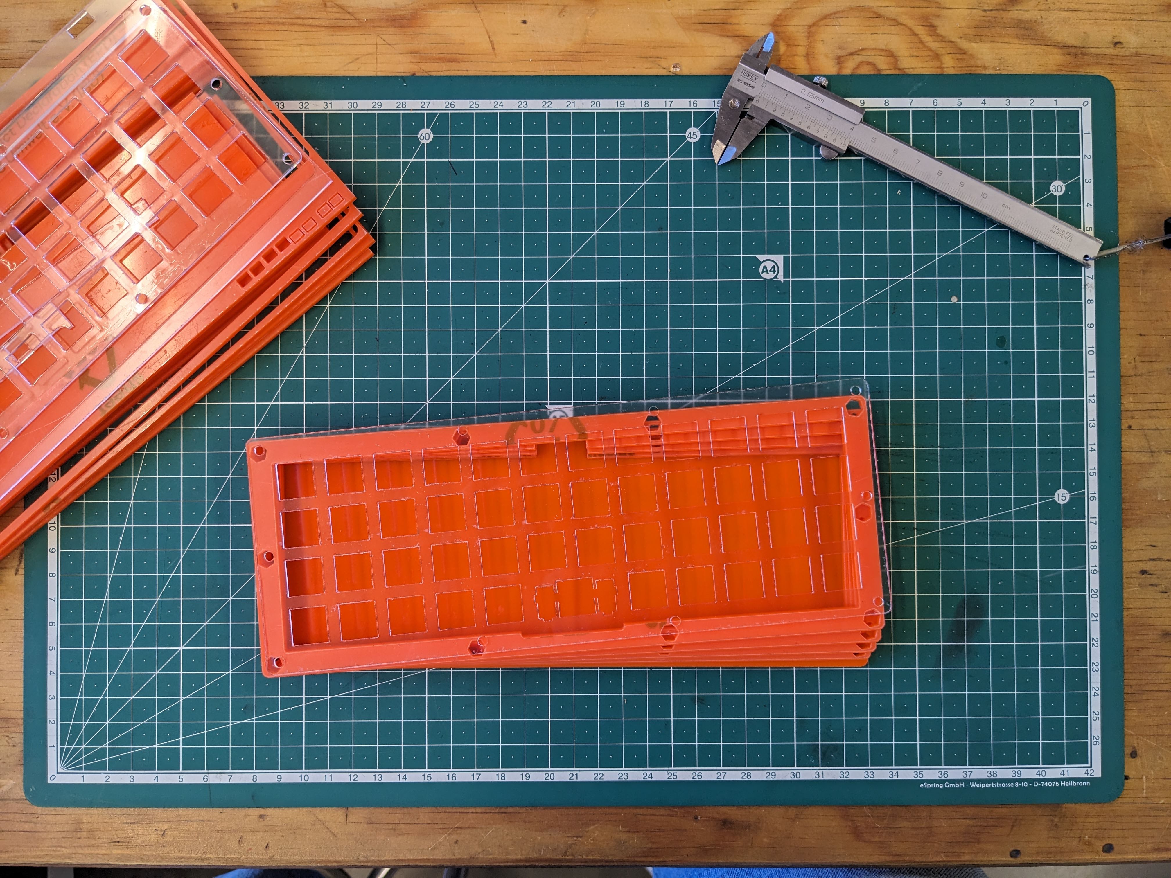
The process of laser cutting and laser engraving the case!
3D Printing
After that, I exported from Inventor the .stl file for the USB C Hub and proceeded with the print in multiple colors to see which one was my favorite. I went with white.
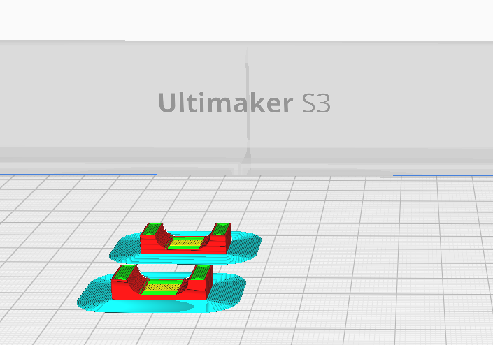
My USB-C hub in the Ultimaker Cura printing software
The soldering
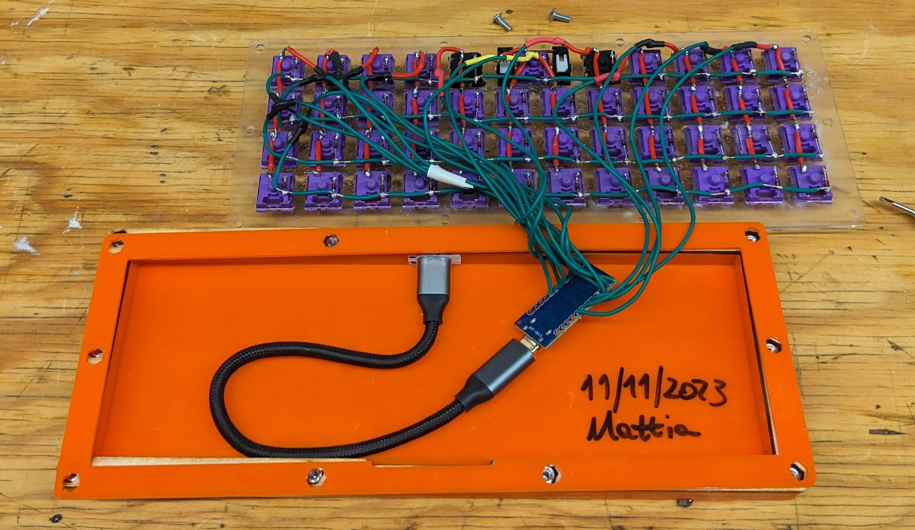
This part was tough. A lot to solder. The goal is to wire up each row and column and feed these wires into the microcontroller. With proper software, the microcontroller is able to identify the coordinates of the pressed key. To make sure there are no ghost clicks is important to have diodes paired with each key. This way current can flow only one way and we make sure that only one combination of row and column numbers corresponds to one key.

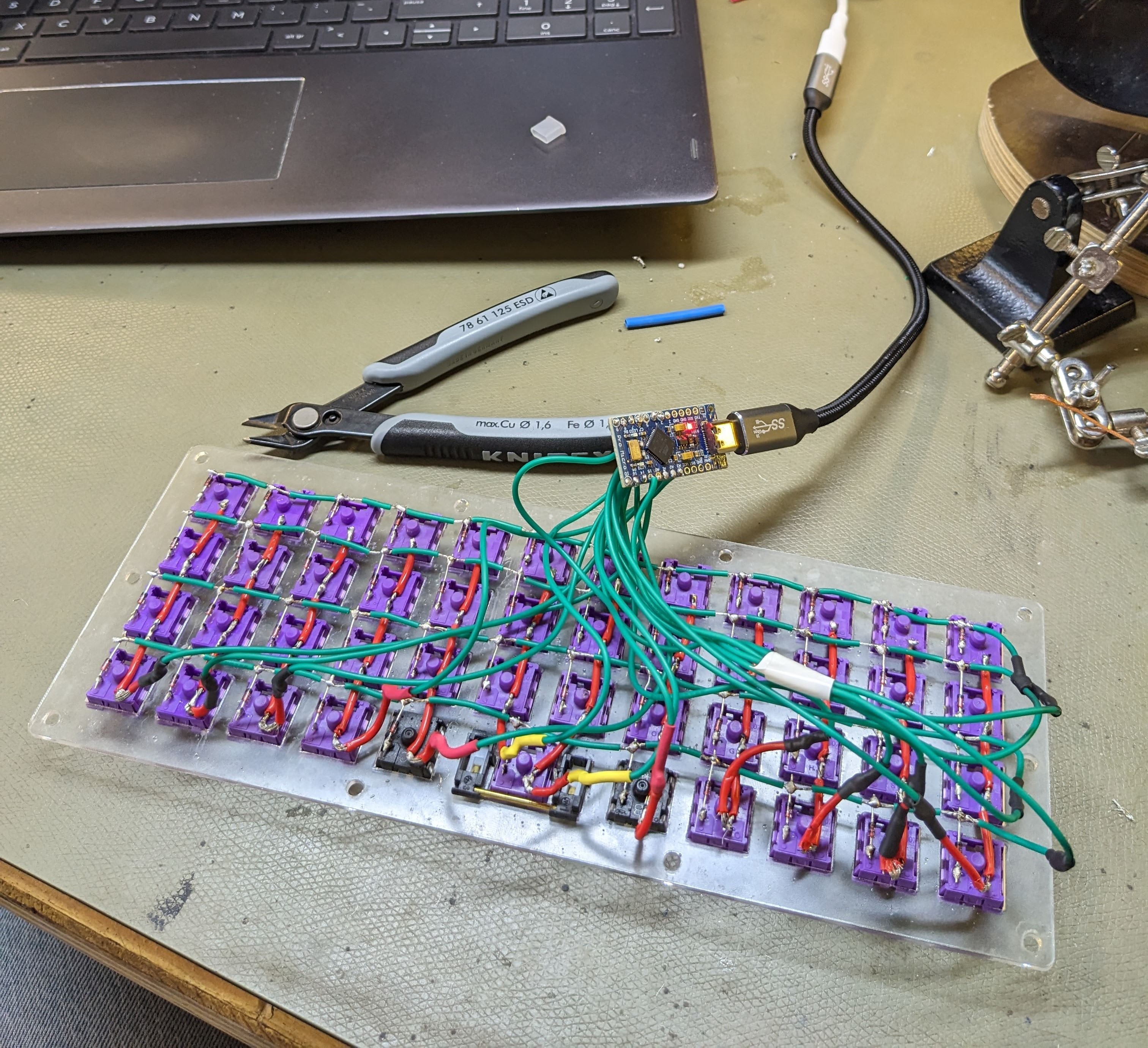
Before and after soldering!
Building everything together
This is the fun part of every project: the moment everything comes together. It is so satisfying to see the result of what some (a lot) hours in the free time can lead to. This was my favorite project so far and I can’t wait to iterate and make some perfections!
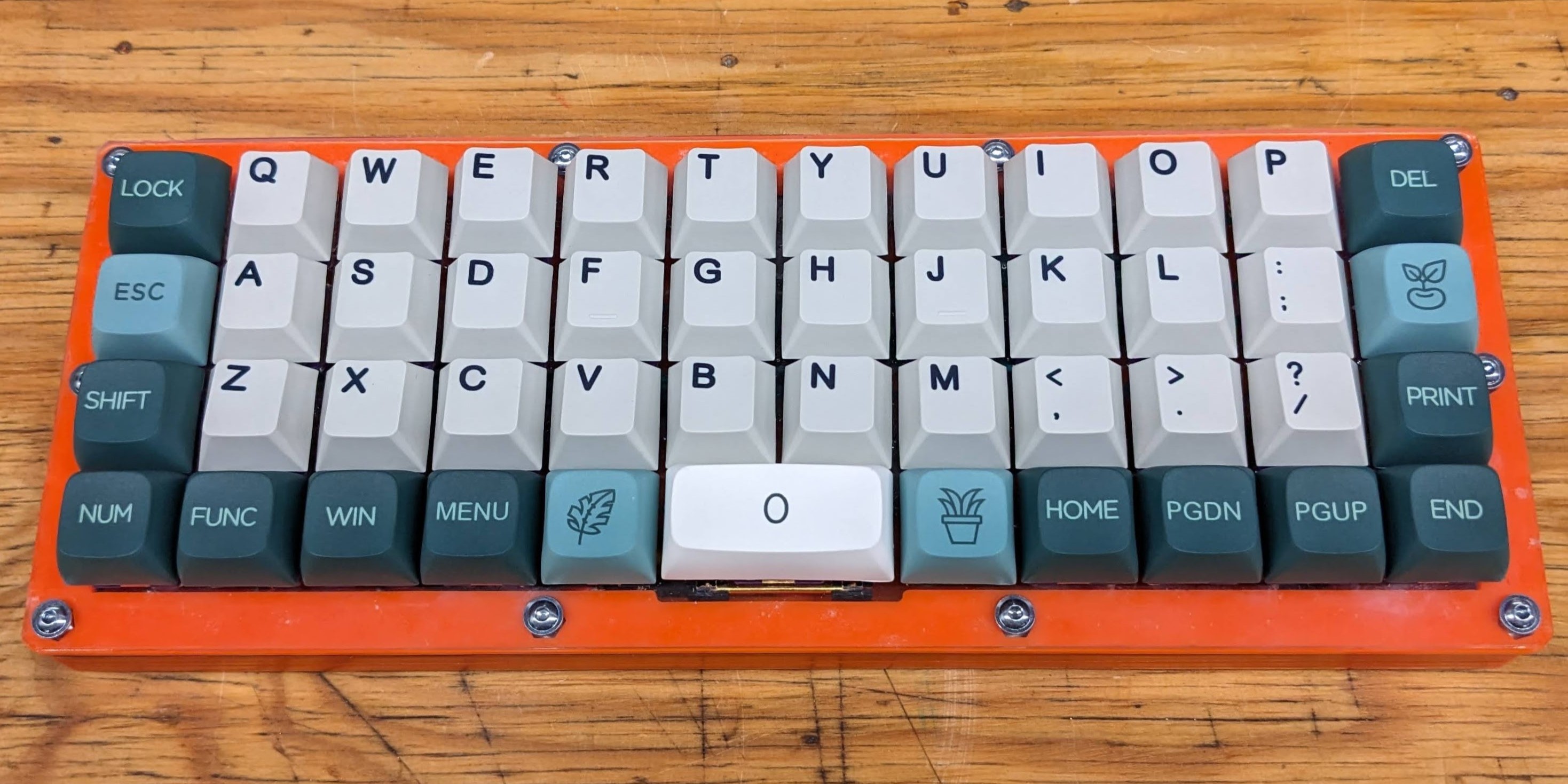
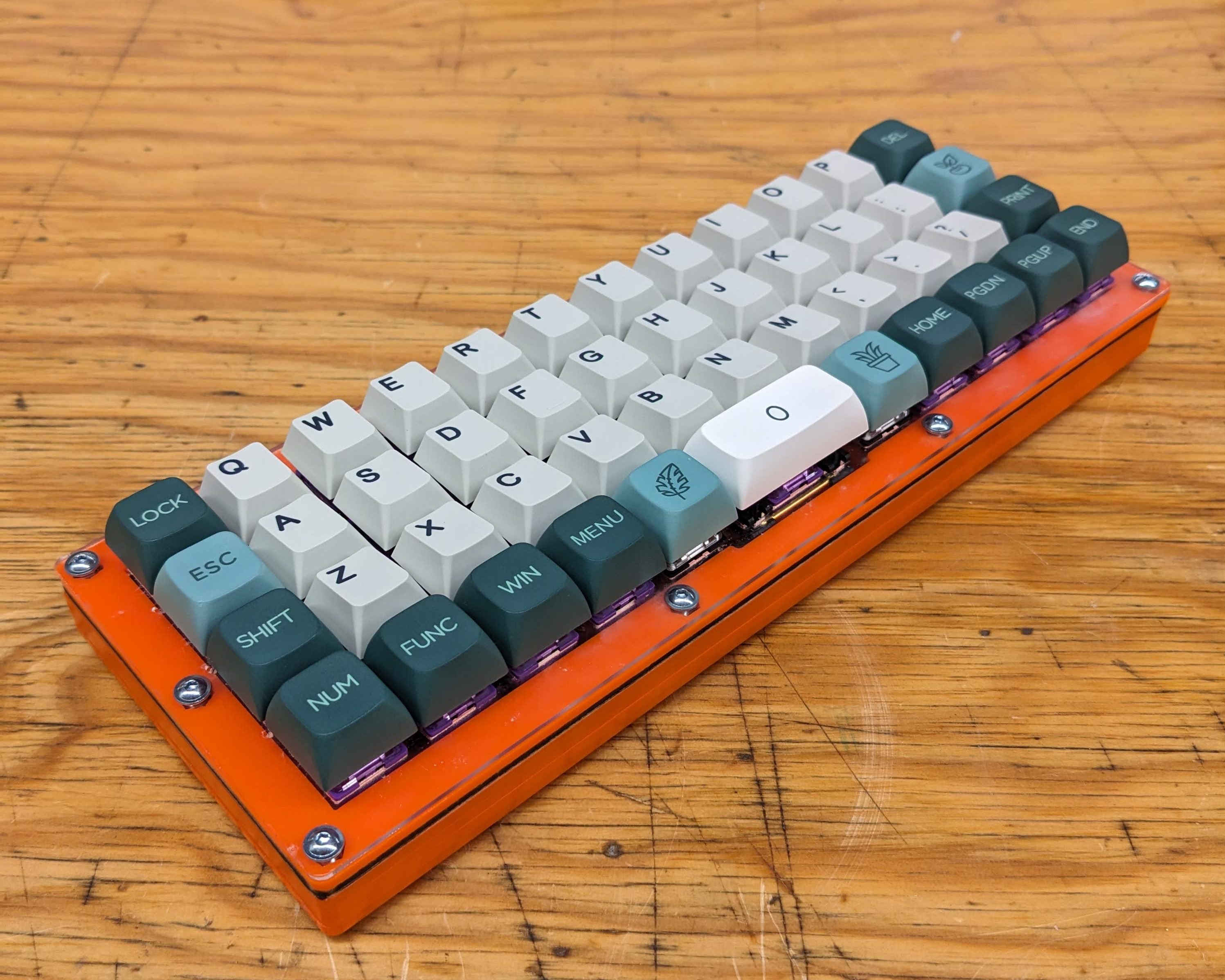

Assembling everything together!
The Files
Here can you find everything you’ll need to complete your version of my design. Make sure to show me your results if you plan to do this yourself!


